In the electronics, we use a variety of test equipment and an oscilloscope is one of the most commonly used pieces of equipment. When using the oscilloscope, we use the probe to measure physical factors such as time, frequency, and voltage. But have you ever wondered how the probe measures these physical factors?
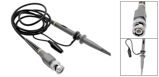
To solve this question, we must tear down the oscilloscope probe and look inside. The probe uses a BNC connector with shielded cable to interface with the oscilloscope. If you used two wires to connect the to the oscilloscope instead, signal distortion would occur. In the extreme a square wave input could result in a sawtooth wave! How could this happen?
Oscilloscopes generally use a higher input impedance to reduce the impact on the test circuit. Therefore, you will see a 1M ohm resistor or a similar circuit behind the probe's BNC connector. There is a small capacitance that will form a filter at input interface, this causes measurable waveform distortion. The way to solve this problem depends on the way the probe is designed.
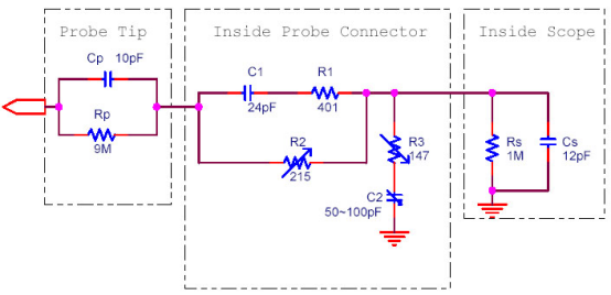
In general, the oscilloscope's probe will use a parallel adjustable capacitor to offset the impact of this part of the cable, some probes have compensation capacitors that allow us to adjust it to reach an ideal effect. If there is a square wave source on your oscilloscope, you can hook the probe on the signal source and adjust the capacitor so that the square wave displayed on the screen becomes the most perfect "square wave". A large capacitor allows the probe to form a low-pass filter and, conversely it will form a high-pass filter. So be careful to adjust the probe to achieve the best results.
Most probes will have a switchable attenuator for attenuating the signal for reading higher voltages. For example, if you select a 10x attenuator and you measure a 1V signal, the scope will show 100mV. You need to ensure that your oscilloscope input is set to the same attenuator setting as the probe so that the displayed signal voltage will be correct.
The probe uses high-impedance circuitry to ensure that the measured circuitry is not disturbed by the measurement section, but sometimes we might need to measure circuits with a low-impedance test. For example, a 50-ohm impedance RF output circuit, an ordinary oscilloscope probe is not usually suitable for this measurement. You need to use a three-way BNC to match the 50-ohm end resistance, and directly connect to the 50-ohm output at the other end.
Related News
- Invitation | Owon invites you to the electronica exhibition. Visit us at A3 667!
- OWON Hong Kong Autumn Electronics Fair Concluded Successfully!Here's A Brief R..
- OWON Invites You To The Hong Kong Electronics Fair Autumn Edition 2024
- OWON Launches New OWH67 High-Power Programmable DC Power Supply
- Master With Precision|OWON Launches HDS120 Multi Functional Oscilloscope Multi..
- Silent Operation, Silent Power | OWON SPS Series Single-Channel Programmable D..
- Successful ending | The excitement never ends and we look forward to seeing yo..
- Inviting You To The Automotive Test Expo--Your Arrival Is Anticipated
- OWON Sincerely Invites You To Participate in The Middle East Educational Techn..
- OWON Sincerely Invite You To Hong Kong Autumn Electronics Fair